Mycroft Mark II Teardown and Pi Upgrade/Replacement
Note: This is a guest post from Chance Rosenthal with the OVOS Foundation.
Caution: don’t do this!
If, for some reason, you need to bust open and disassemble your Mark II in spite of that warning, here are some annotated photographs of just that process. Midway, we’ll swap out the factory Pi for an 8GB model to facilitate offline performance.
Note about screws
There are several different screws in play here. I strongly advise you keep multiple containers at hand so that you can keep them apart. Fortunately, it isn’t too hard to remember which ones go where. Unfortunately, I forgot to document the difference while taking these photos.
Acknowledgements
Special thanks to NeonAI for providing the hardware involved with this demonstration, and to Mike for hosting the results while OVOS' blog is being overhauled.
In the course of this operation, we upgraded one unit belonging to the OVOS Foundation and one belonging to Neon. At least two other members of our organizations have done this independently, to universally satisfactory results, but we nevertheless cannot endorse the practice of doing end-user surgery on a device that can’t be replaced. Do this at your Mark II’s peril, or if something already needs replacing.
Tools required
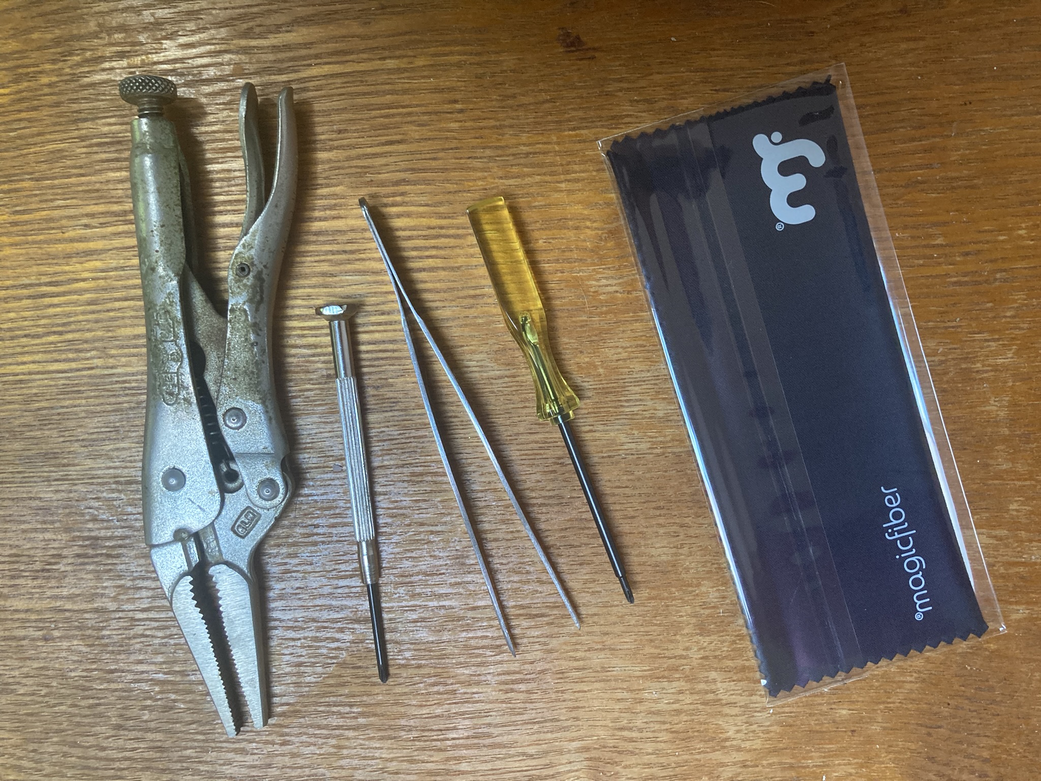
- A magnetic #00 Phillips (you really want it to be magnetic)
- A long and thin #00 Phillips, if your magnetic screwdriver is not long and thin, or if you don’t want to damage its handle
- Vice grips, to grab the thin screwdriver and loosen some evidently machine-tightened chassis screws that are difficult to reach
- Forceps
- Soft cloth, ideally microfiber, to protect the screen (optional, strongly advised)
Preparation
Gather your tools. Shut the Mark II down and unplug it. Disconnect any peripherals and USB storage devices.
I also like to keep a few small containers nearby to hold the screws and small parts I remove from the device. Clean spice jars and empty mint tins are ideal for this purpose.
Contents
Screen Assembly


Lay the device on its back, with the screen to your left and the speakers to your right. Remove two very small screws from its bottom edge.
Grasp the bevel holding the screen. Gently lift the bottom edge of the screen assembly, as shown in the third image.
Carefully move the screen assembly toward the bottom of the chassis to release it, as shown in the fourth image. You may now set it gently back down on the rest of the chassis, as shown in the fifth image.


Slowly lift the near (left) edge of the screen assembly, revealing two ribbon cables, as shown in the first image above. Holding the screen assembly in this position with one hand, use the forceps or a thumbnail to loosen the black fastener holding the white and blue ribbon cable to the Raspberry Pi, as depicted in the second and third images. Gently remove the ribbon cable from its socket.


Now you can remove the ribbon cable from the grey clip that routes it along the speaker housing. Once you’ve done that, there’s enough slack in the other ribbon cable to free the screen assembly entirely. Carefully lean it against the far (right) edge of the chassis.
Read carefully before continuing: Study the second and third images. You should lift the screen assembly, turn the chassis so the speakers are facing the back of your bench, and finally lay the screen assembly on the soft cloth as shown in the third image.
Speaker Housing


Remove one screw and plastic washer from the top left corner of the speaker housing, and another from the top right corner.


Now it’s time to remove those long plastic posts that run along the bottom edges. I needed to apply a fair bit of torque to loosen these; this is where I used the long metal screwdriver and the Vice Grips.


With the screw removed from the post, you can lift it most of the way out. Then tilt it a little to get the corner around the speaker housing.

I find it helpful at this point to disconnect the upper speaker connector (shown at left.) The lower connectors in both of the units I’ve opened have been attached to longer cords, so you can leave the lower one connected for the time being. If you decide to disconnect both, mark them so you don’t mix them up for reassembly.
You can now remove the speaker assembly. Carefully set it next to the unit, taking care not to put any stress on the cord still connected.
Raspberry Pi and Top Assembly
Remove the screw and plastic washer from the white plastic bracket holding the Raspberry Pi to the back of the chassis. The bracket will remain attached to the Raspberry Pi.


Carefully disconnect the fan from the SJ-201 daughterboard (the big circuit board under the top of the chassis) as depicted at left.
Remove a screw from each of the corner posts holding the top of the chassis to the back, as seen in the center photo.
Slowly, taking care not to stress the speaker cable that’s still attached, slide the top up and off the back of the chassis. The SJ-201 will still be attached to the top, and the Raspberry Pi will still be attached to the 201, as shown at right.


Carefully remove the Raspberry Pi from the SJ-201 daughterboard, leaving you with the left image: the daughterboard, affixed to the top of the chassis, with one speaker connector attached. Gently lean the top assembly against the speaker assembly, as depicted at right, taking care not to put any pressure on the buttons.

If you’re replacing the Raspberry Pi, you need to transfer this bracket. Note the orientation.
You can also now replace the fan. Consumer replacement of the SJ-201 daughterboard is not possible, so I haven’t documented it.
Reassembling your Mark II
Reassembly is just the reverse of the above. I started out with photos of the reassembly process, but it made this guide excessively long without adding much value; if somebody’s having trouble reassembling their speaker, please reach out to the OVOS crew (or to ChanceNCounter directly) for pointers.
I do have a few tips:


Reconnecting the lower ribbon before you reinsert the speaker assembly makes routing much easier.

Patient use of a magnetic screwdriver allows you to drop those little plastic washers right on target.

There is a perfect angle for replacing the front, and I think it’s about here.
Afterword
Replacing the included 2GB Pi with an 8GB model may have been overkill, but it allows Neon to run offline at warp speed. You’ve also probably noticed along the way that accessing the SD card slot isn’t so bad; it’s not something we can recommend to consumers or end users, but if you’ve gotten all the way through this teardown, you can do it. Whether that’s preferable to the storage device you’re currently using depends on your current device.
I hope this guide has been helpful. Please let the Neon crew know if we’ve left anything out!